English
 简体中文
简体中文
 繁體中文
繁體中文
 Français
 Español
 عربي ،
 русский язык
 Português
 Deutsch

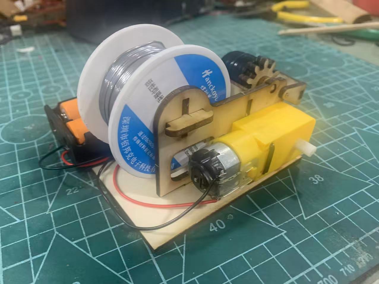
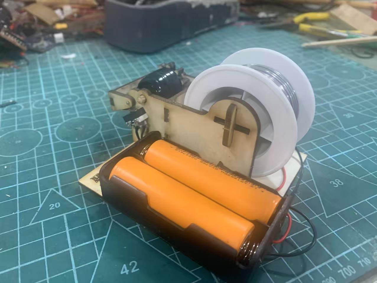
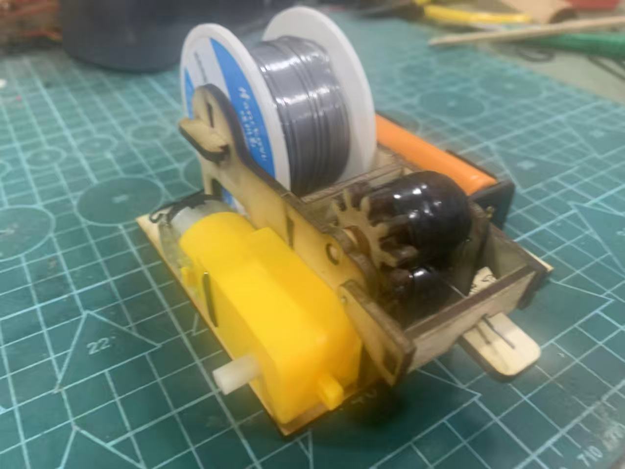
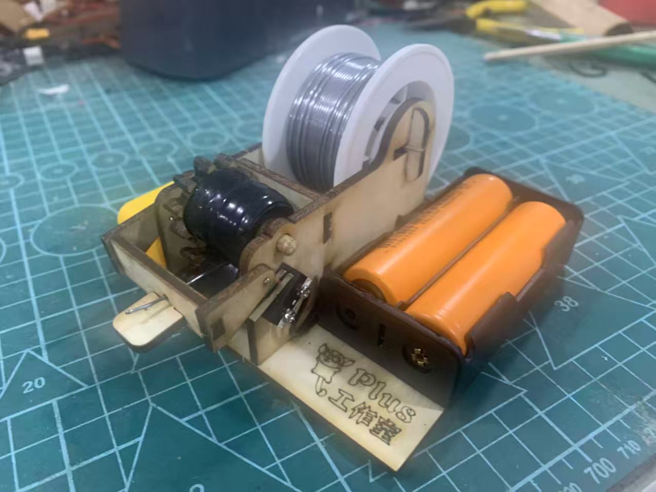
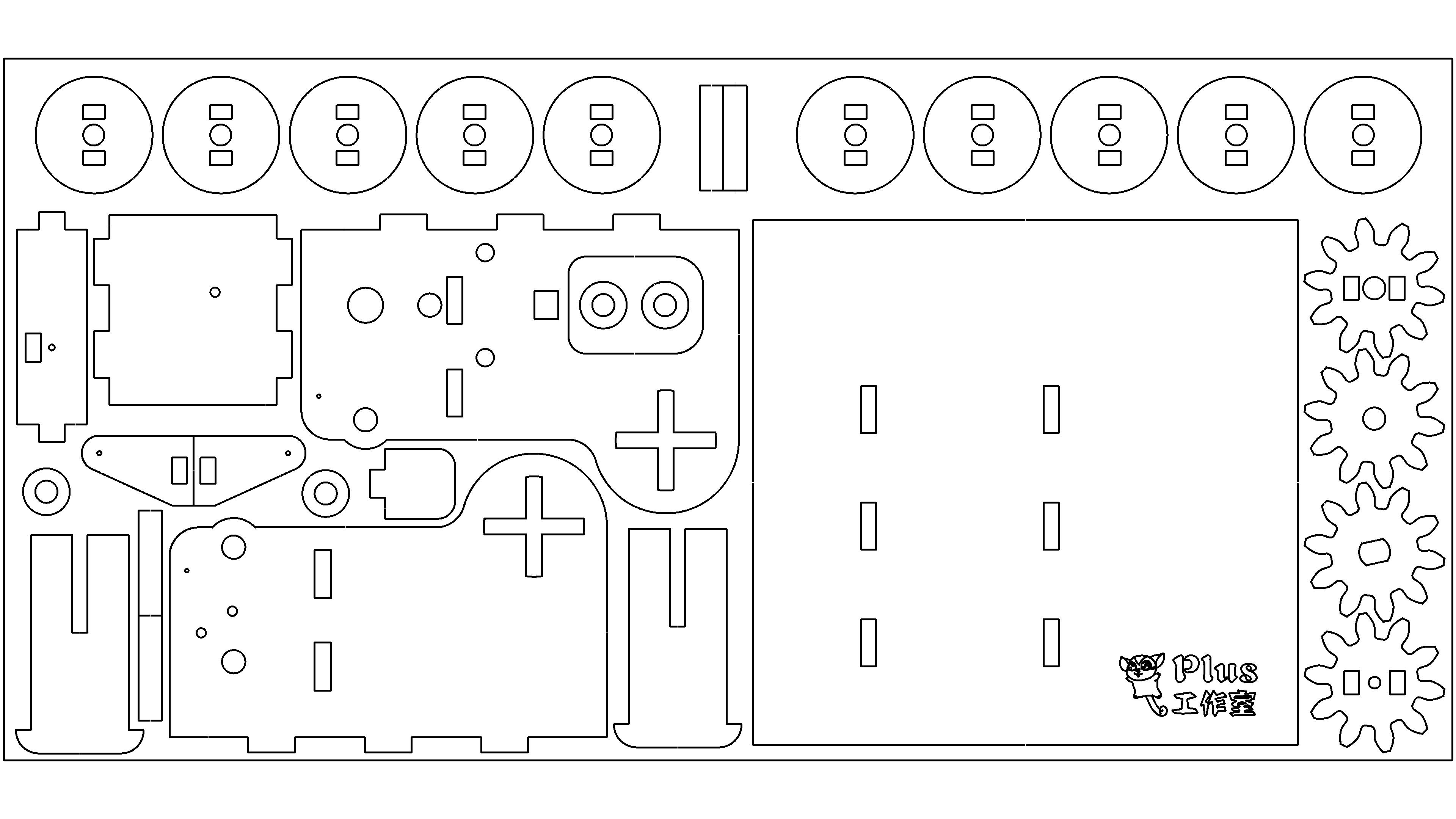
Electric soldering wire feeding mechanism (self-made by Maker)
1. Corresponding functions of each component
1. White Plate: Solder Wire Roll
Baibangke0.8mmActive solder wire is a welding consumable that is wrapped around a plastic wire spool.
2. Yellow reduction gear motor
The power core is driven by a wooden gear set to rotate the spool and push the tin wire at a constant speed.
3. Wooden laser cutting frame
The supporting frame of the entire structure is assembled with laser cut wooden boards, in the style of self-made teaching aids by the maker.
4. 18650Dual battery box
Portable power supply, no need for external power supply, suitable for outdoor welding and laboratory manual use.
5. Bottom toggle switch+contact point
Control the start stop of the motor, toggle the switch to rotate the motor, automatically send out the solder wire, and release the power to stop sending.
2. Core Purpose
Basic functions
Manual welding auxiliary tool, automatic uniform tin feeding:
Traditional welding requires holding an electric soldering iron with one hand and pinching the solder wire with the other hand, and operating with both hands is crowded; This device fixes the tin wire on the online tray, and the motor automatically sends tin forward. With just one hand holding the soldering iron, the tin length can be accurately controlled, making it easier to solder circuit boards, maker models, and electronic teaching aids.
Teaching scenario adaptation (applicable to your science and technology innovation course)
1. Physics knowledge points: gear motor transmission, gear meshing, simple circuit on-off, mechanical energy conversion;
2. Engineering practice: laser cutting structure design, assembly tolerance debugging, simple automation mechanism;
3. Practical labor: Basic training in electronic welding to reduce the difficulty of novice welding.
3. workflow
Turn the bottom switch → the battery supplies power to the reduction motor → the gear drives the tin wire disc to rotate → the solder wire is sent forward at a constant speed → the soldering iron contacts the solder wire and melts it for welding; Release the switch and the motor immediately stops running, causing the tin wire to stop feeding.
4. Design Highlights (Advantages of Maker Teaching Tools)
• All wood assembly, detachable, students can intuitively understand the gear transmission structure;
• Portable lithium battery power supply, can be used in classrooms and outdoor science and technology innovation competitions;
• The structure can be modified twice: changing the gear to change the wire feeding speed, and installing a potentiometer for speed regulation.
Note:
1Bring your own.m2*8Two screws are used to fix the micro touch switch, self providedm4Two screws (or4mmA wooden stick is used as a friction wheel rotating shaft.
2Use a small amount of electrical tape to wrap around the friction wheel to increase friction.
3Used in the sample1:120ofttMotor coordination18650Two batteries.
4The current compensation correction applies to approximately2.8mmThick composite board.
5This design is compatible with50Packaging of welding wire rolls. Solder coil size outer diameter55mmThickness28mm, inner hole diameter20-24mmIf combined with other sizes of solder coils, the design needs to be modified.