 English
 简体中文
简体中文
 繁體中文
繁體中文
 Français
 Español
 عربي ،
 русский язык
 Português
 Deutsch

drawing
Long March No.1(1:41Laser cutting model design project



Drawing Information
Drawing video
Drawing Description
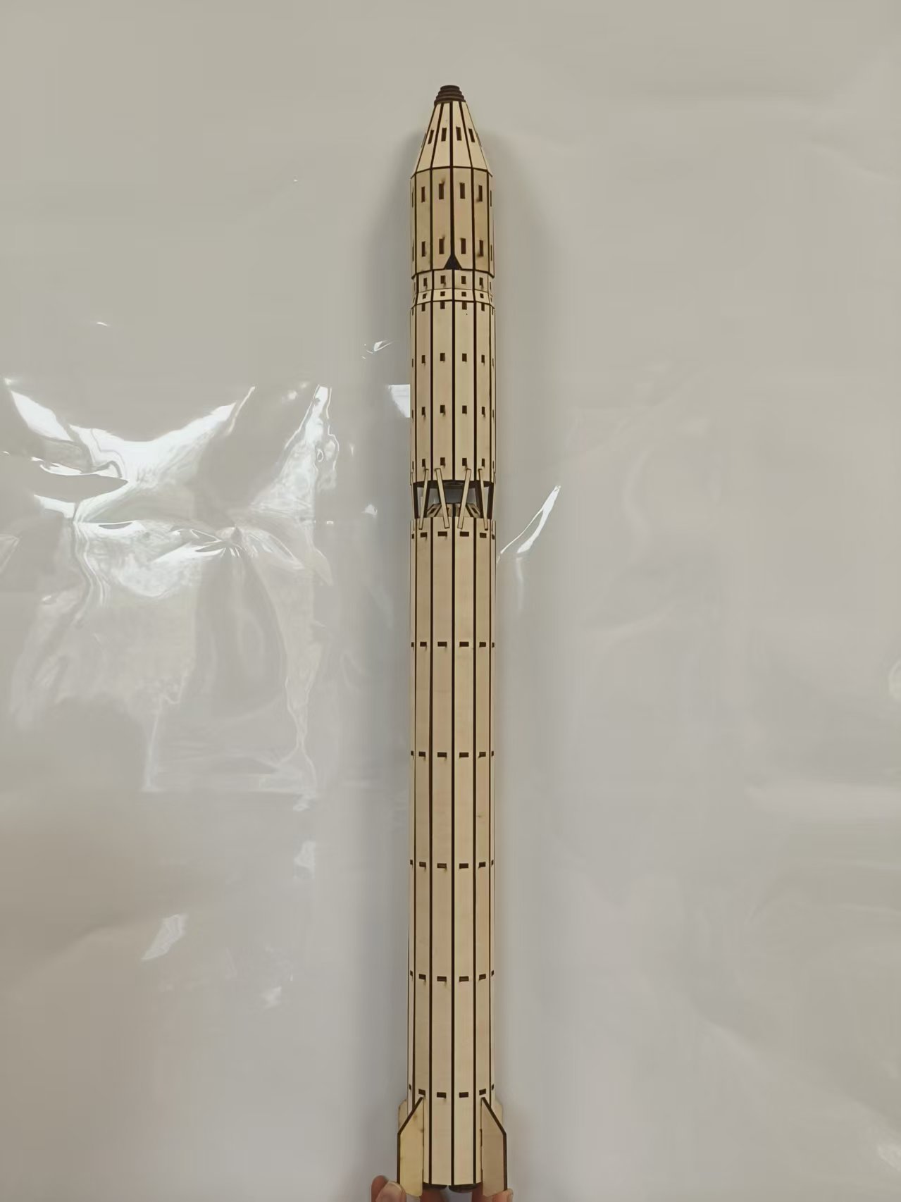
If I were to choose an aerospace theme, I would think of space stations, spacecraft, airplanes, spaceships, and even radio telescopes in my mind. The scope of aerospace themes is too vast, and I don't know what to do for a while. So ultimately, I chose to replicate the origin of China's aerospace industry, which is our country20century70The first generation and first type of carrier rocket, Long March 1, was prepared for the launch of the first artificial satellite.
In order to distinguish myself from mainstream rocket models online, I try not to use plastic pipes or3DPrinted copies should be used as much as possible3mmThe oak board completes all the rocket making. And I will do my best to restore its details.
The shell design of the entire rocket is relatively simple, so I will focus most of the design on the following points:
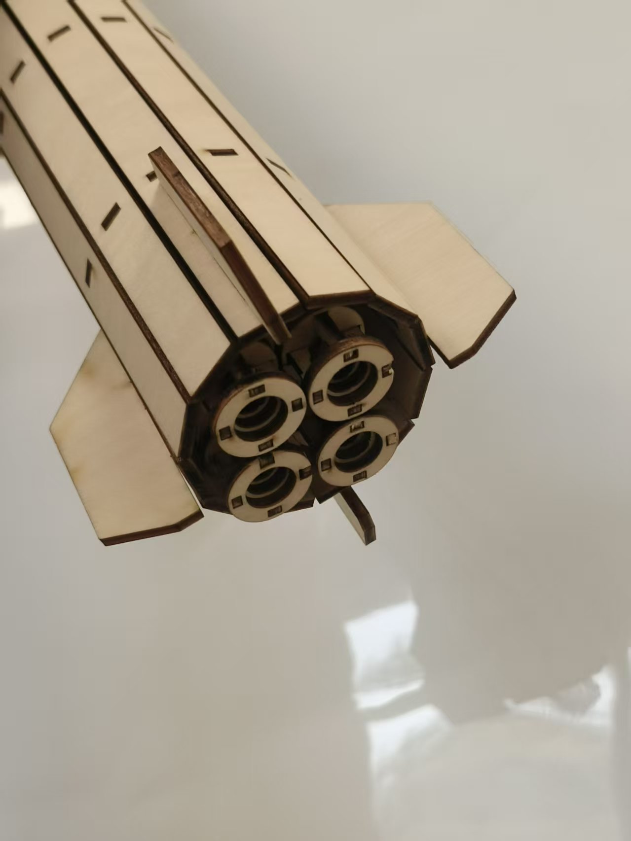
1.A movable first stage rocket booster: I hope to simulate the effect of a vector engine.
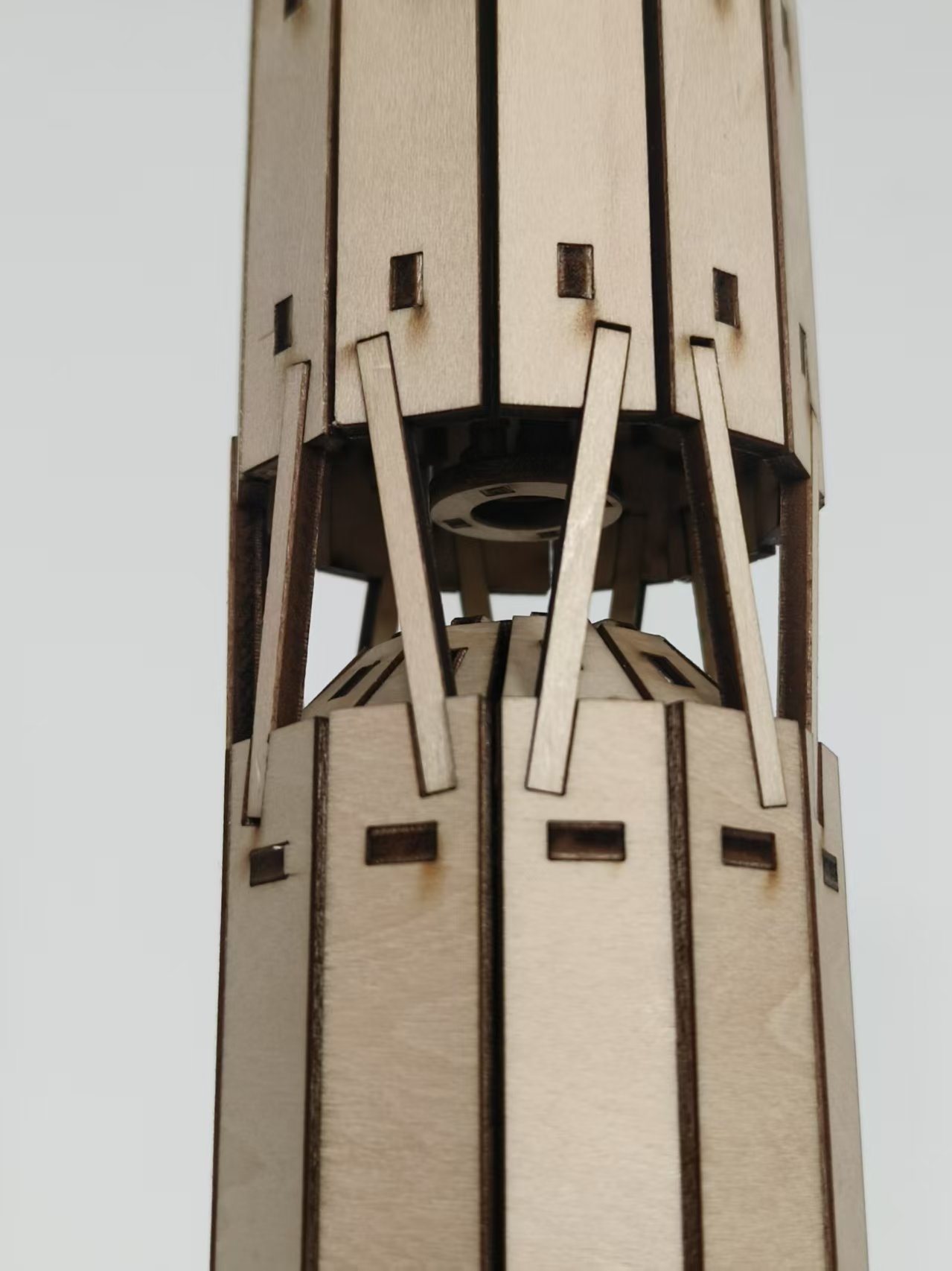
2.The upper part of the oxidizer tank exposed by the first stage rocket: In the searched network diagram, there are two parts of oxidizer tank and fuel tank in the first stage rocket, with the oxidizer tank exposed in the rod system. I have also restored this detail.
3The linkage part: Perhaps the most outstanding part of this design, and also the innovation point that I value the most. The Long March 1 used explosive bolts to connect the first stage rocket and the second stage rocket, and I also replicated this detail by using3mmConnect the wide wooden strips.3mmThe wide wooden strip is3mmOn the oak board is a wooden stick,1The wooden stick is very fragile and can easily break, which can restore the effect of explosive bolts.1The wooden stick is very fragile, but12A wooden stick can firmly lift a rocket, and if it accidentally breaks, it can be replaced.
4.The opening and closing structure of the fairing: This is also an innovative point that I particularly value. I did not design a complete fairing, but rather a structure that can be split in half. And, in order to ensure that the parts are not lost, I used a connecting rod structure, which not only achieves the desired effect but also prevents the parts from being lost.
related activities
This laser cutting design participated in the activity: Interstellar Creativity, Intelligent Future Creation "- Aerospace themed Laser Creation Competition
drawing documents
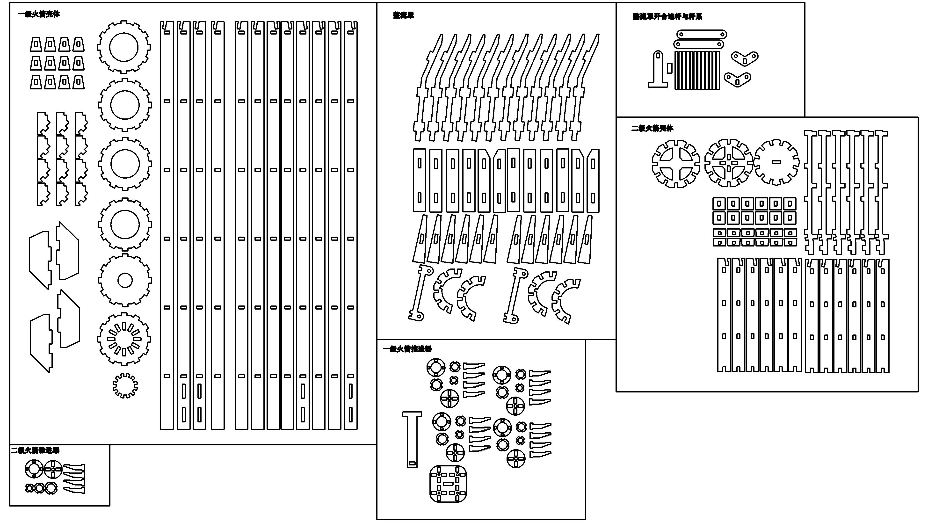
Long March No.1(1:41Laser cutting model) overall drawing (uncompensated)
Basic Parameters
process parameters
| Processing Technology | processed material | pattern | power(%) | speed(mm/s) | processing times |
|---|---|---|---|---|---|
| cutting | 3mmBasswood board | Horizontal unidirectional | 99 | 40 | 1 |
| Draw lines | 3mmBasswood board | Horizontal unidirectional | 5 | 300 | 1 |
Contour image extraction
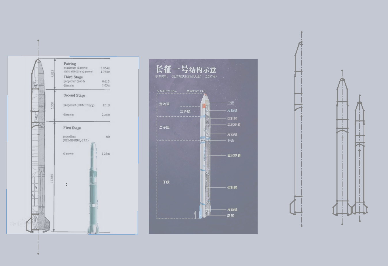
SOILDWORKS2020Create a new assembly in the middle, create new parts in the assembly, and create a new sketch. Use the sketch image tool to import the image of Long March 1 and set it to semi transparent. Draw the outline of Long March 1 by comparing it with the outline on the image, and scale it to the appropriate size.
Modeling the shell of a first stage rocket
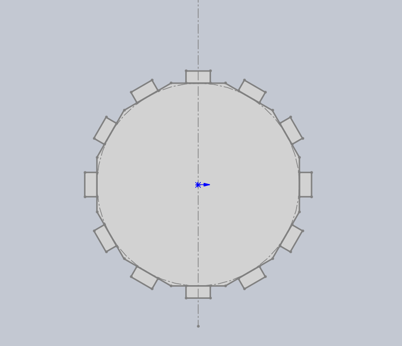
Based on the previously determined outline dimensions, I first drew a12Edge shape, and here12Draw protrusions on the edges of the strip for insertion.
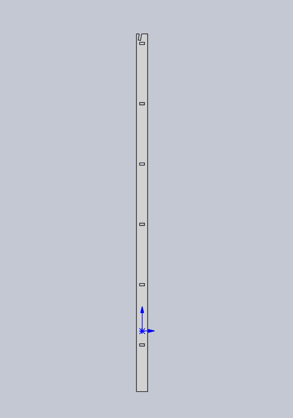
Then draw1Bar width and12A rectangle with the same edge and a groove dug at a designated location.
Subsequently12Linear array of edges and circular array of rectangles directly obtain the shell.
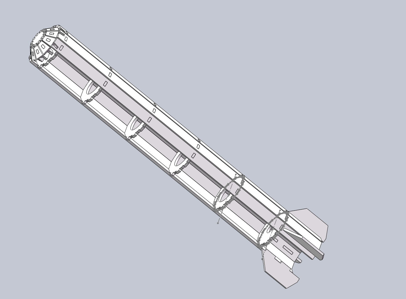
In order to install the tail wing, I also dug a groove at the bottom of some rectangles.
To install the pole system, I also divided the rectangle intoA,BTwo types, dig grooves with different directions at the top.
I still have12A certain groove has been dug out in the edge shape, and in the middle12The deformed groove is only for aesthetics, the bottom is12The edge groove is designed to facilitate the free movement of the thruster, and the top is12The edge groove is designed for easy sealing.
Modeling a first stage rocket propulsion system
This is also the most difficult part to assemble in the entire design.
In order to restore the Long March 1 as much as possible, I also adopted a quadruple assembly on the first stage rocket propulsion system and adjusted it to a freely movable form. Each rocket booster is the same and is made up of stacked rings of different sizes. I dug in all four directions of the circular ring1mmThe groove is designed with four fixed brackets, which also have1mmThe notch.
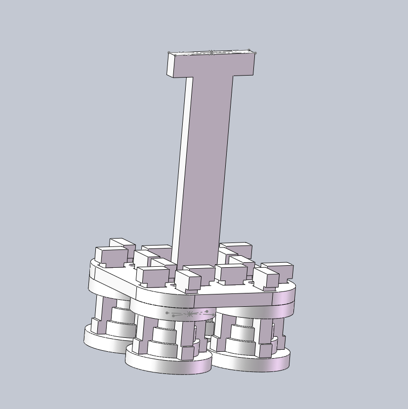
Modeling the shell of a two-stage rocket
The second stage rocket is much shorter than the first stage rocket, but the shell of the second stage rocket is not flat and needs to be bent at one position. For the wooden board, it needs to be designed in sections. So I used a different modeling method than the first stage rocket, first drawing the fixed frame of each shell.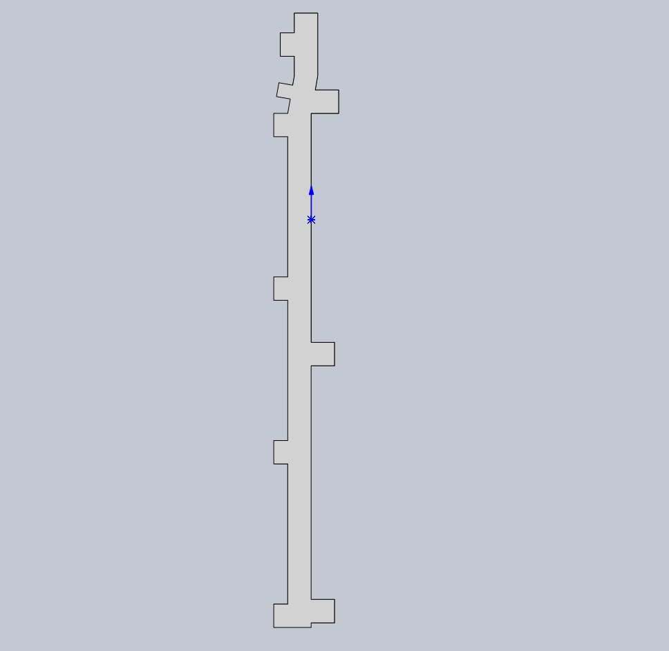
Then draw the one on the fixed frame3Cut wooden boards and dig grooves. Draw again12Edge shape, using linear and circular arrays to complete the shell production.
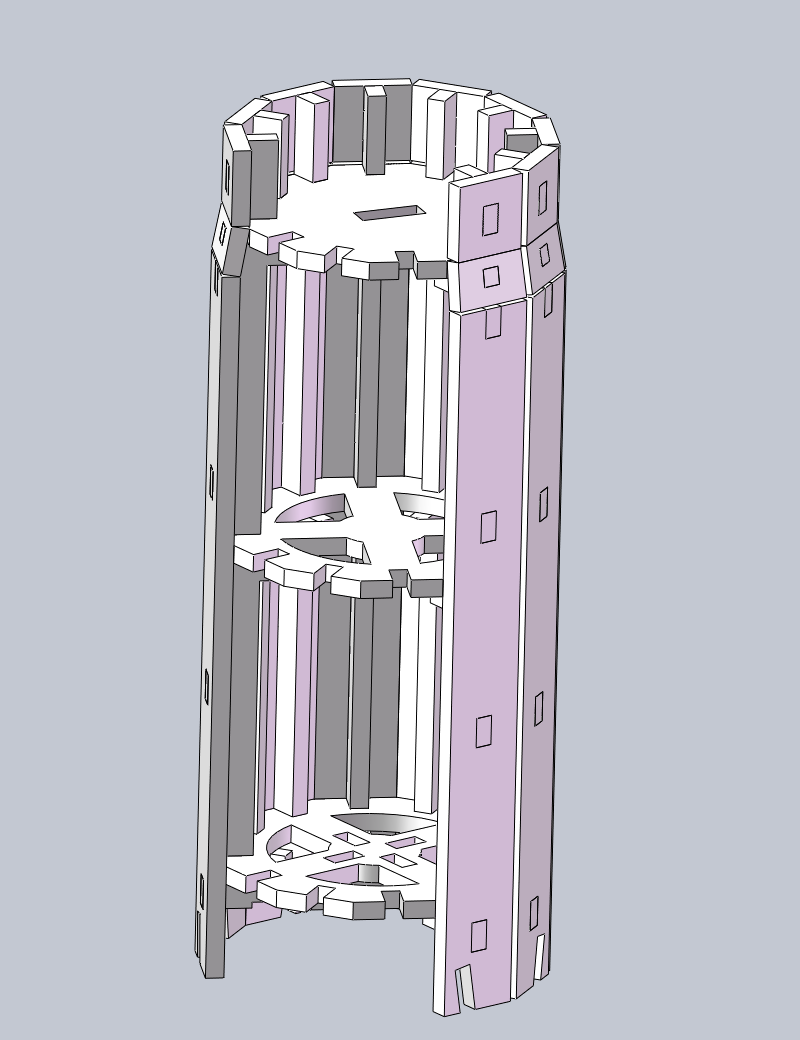
Secondary rocket propulsion system
In fact, the second stage rocket thruster and the first stage rocket thruster are separate models, but in order to reduce the construction period, I used the same model here.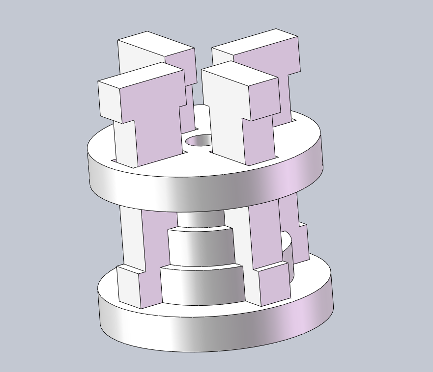
Modeling fairing
It should have had a three-stage rocket (fairing) section, but due to the intricate details of the three-stage rocket and Dongfanghong-1 satellite inside the fairing, I am unable to use it in such a small space3mmI made it out of oak board, so I gave it up3The modeling of the first stage rocket and Dongfanghong-1 satellite only designed a retractable fairing and adopted the same modeling method as the second stage rocket shell.
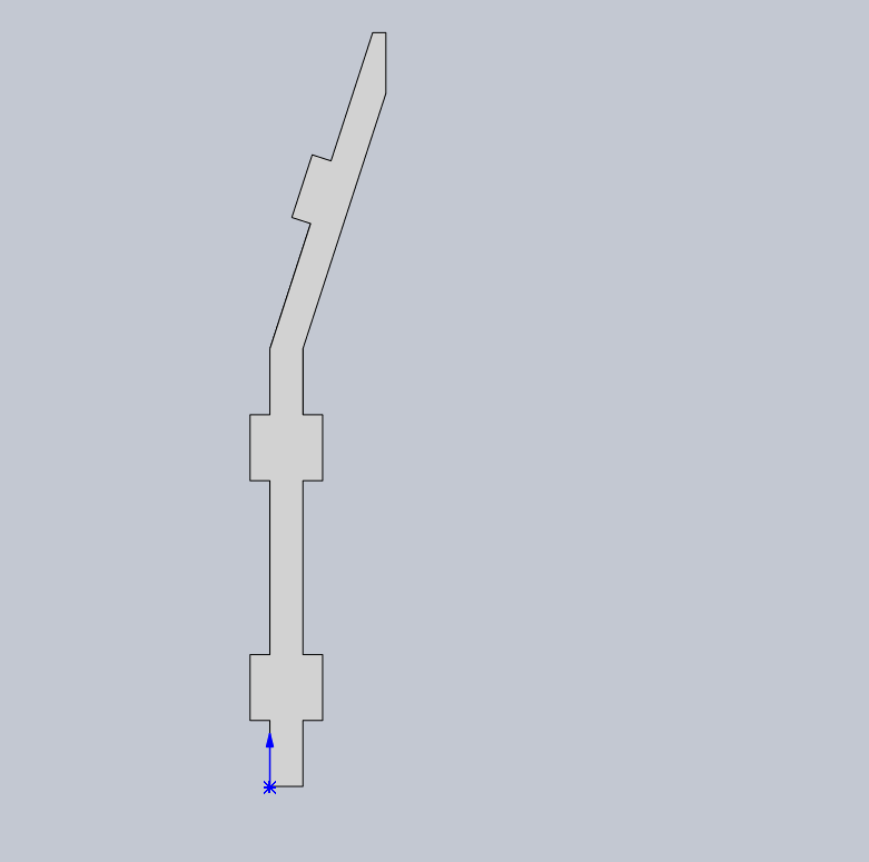
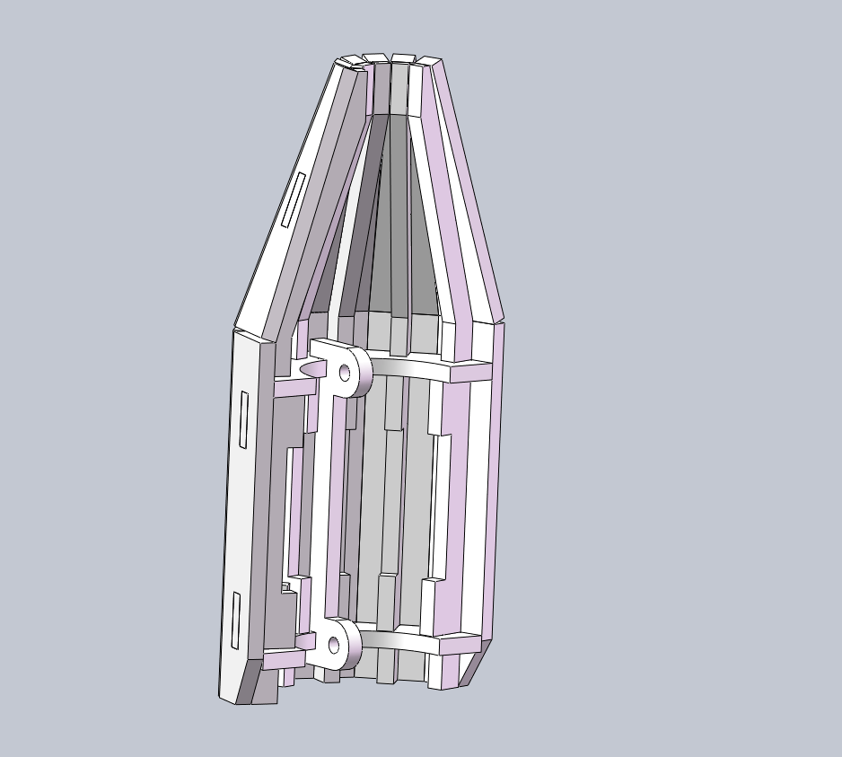
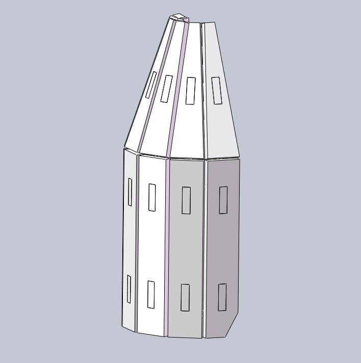
And I have reserved a circular hole position for connecting with the connecting rod through screws, and designed a chamfer on the edge of the shell to prevent collision during opening and closing.
Assembly connection
The above parts are all inSOLILDWORKSDesigned in the subassembly.
Then I pulled all the components back into the overall assembly and connected them.
Part of it is the connection of the fairing.The other part is the connection of the rod system.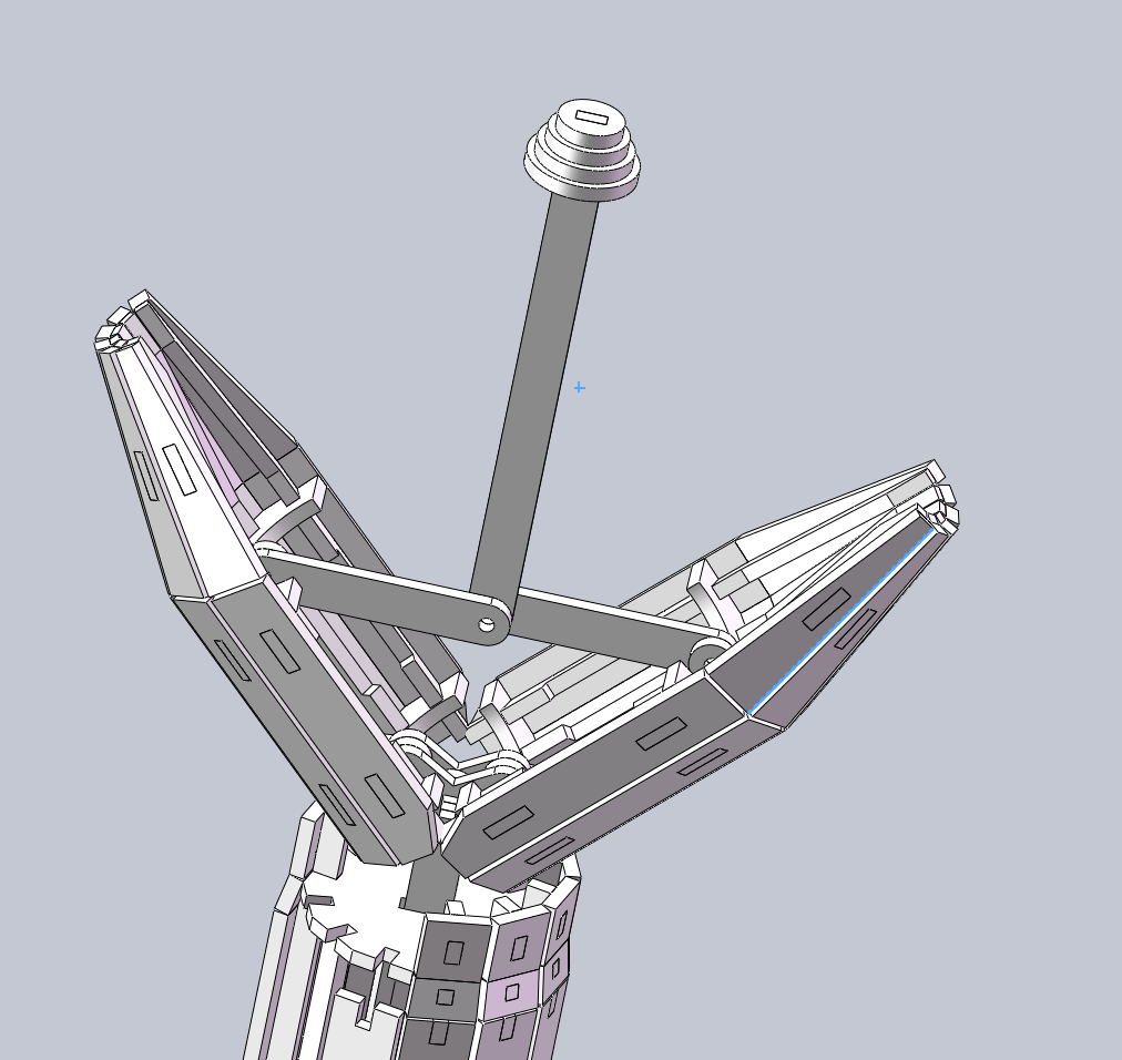
importLaserMaker
SOILDWORKS2020After saving the model as another file, delete all the fittings used for assembly and lay all the parts flat on one plane. Import the engineering drawing file and export it asdxfFormat file, usingLaserMakerOpen and adjust the laser compensation according to the pre tested compensation parameters to ensure that the compensation of all parts is correct.
Precautions
1.I did not perform laser compensation in the released drawings. If you want to replicate, please perform laser compensation based on the specific parameters of the machine.
2.The laser compensation in the entire design needs to be divided into3The file. The first requirement is to loosen it a bit, for the first stage rocket launcher and the second stage rocket launcher; The second level requires moderate requirements and is used in most of the mortise and tenon joints of rockets; The third level requires a tighter fit and is used for assembling the fairing (because the fairing only has two mortise and tenon joints, it is very loose).
3.Please obtain the assembly sequence of rocket thrusters from the photo above.
4.There may be confusion during the assembly of the second stage rocket and fairing, and if spelled incorrectly, it can lead to the failure of rocket assembly. Please note that the shell part of the second stage rocket is located in12Above the edge. The order from low to high in the fairing is semi-circular ring, fixed frame, fixed frame, semi-circular ring. Please observe the picture carefully for the specific order.
make
Material List:
1.3mmLimestone board:450mm×450mm 3Zhang
2.M3×12screw 2piece
3.M3×16screw 3piece
4.M3nylon nut 5piece
Tools:
hammer
screwdriver
Wrench or pliers
Install in the order of first stage rocket launcher, first stage rocket shell, second stage rocket launcher, second stage rocket shell, and fairing.
It is best to use a hammer to assist with installation. The opening and closing structure of the fairing requires screws. Use a wrench or pliers to fix the nylon nut, and then use a screwdriver to tighten the screws.
Related Recommendations


comment (2)
-
classification
Aerospace themed competition event -
copyright
open source licenseCC-BYAllow commercial use; -
Business License
Further information

It seems like it won't open
Can you provide a detailed description?