 English
 简体中文
简体中文
 繁體中文
繁體中文
 Français
 Español
 عربي ،
 русский язык
 Português
 Deutsch

drawing
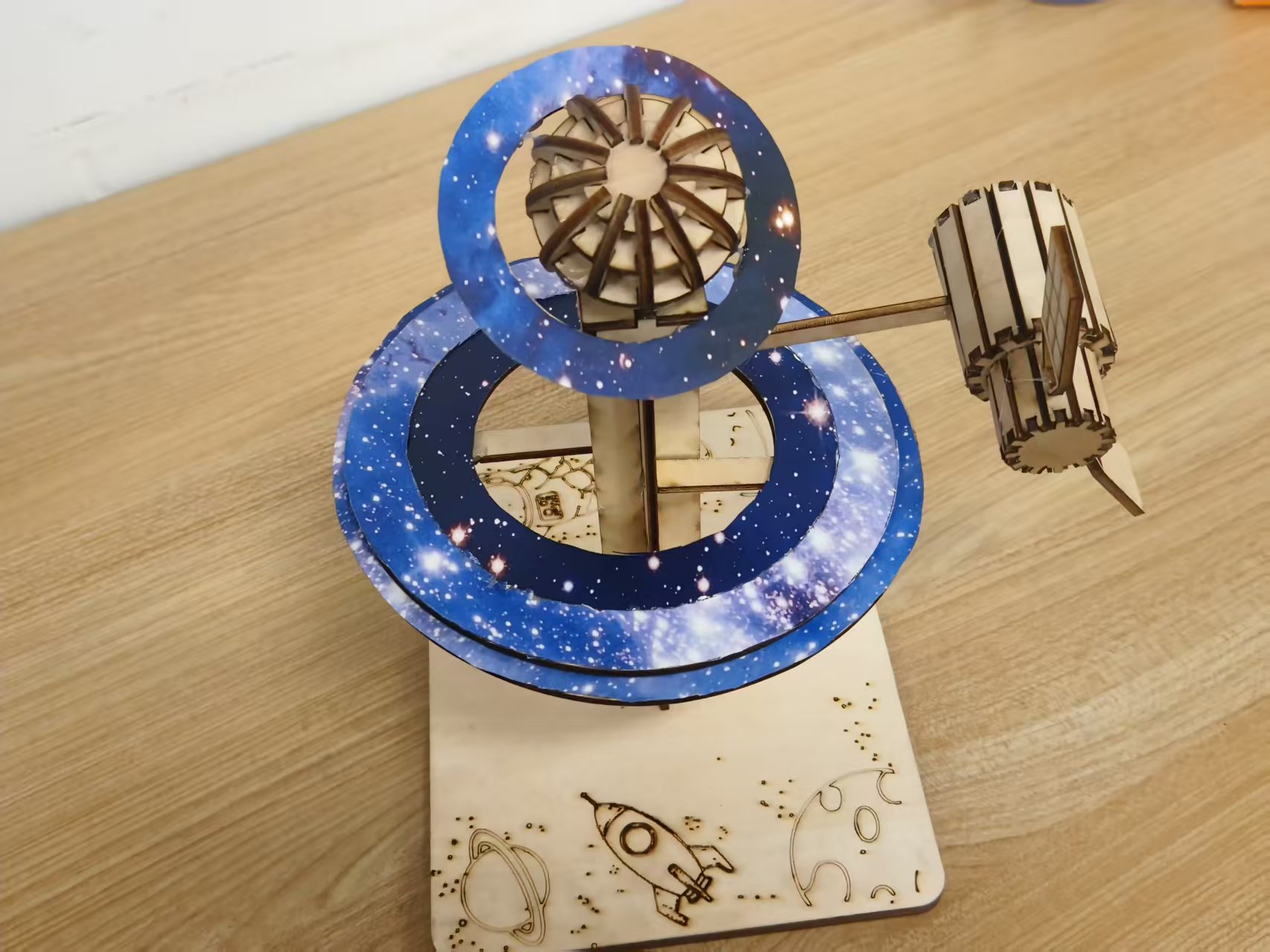
Xinghang Dream Post design project
Drawing Information
Drawing video
Drawing Description
Design philosophy
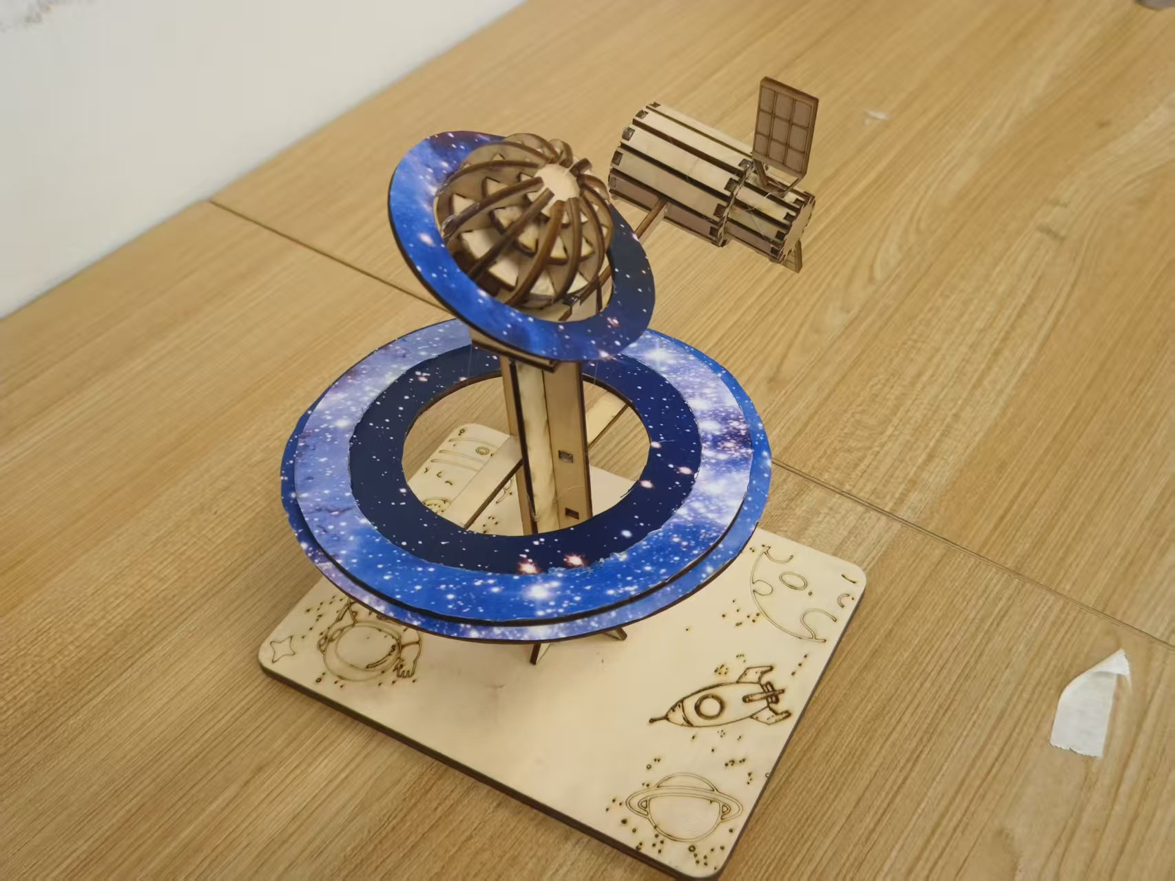
Carving the poetic dimension of the universe with laser technology, viewing satellites as interstellar dreams The 'relay station' weaves a dreamy scene of sailing through the stars, using planetary waterways as threads. The work reconstructs the romantic order of the universe at a microscopic scale, allowing viewers to encounter human space exploration between the orbits of ornaments and satellites Dreams as horses, stars as post stations The poetic journey, in the fusion of technology and art, touches the tenderness of the universe and the passion of exploration.
Source of inspiration
As a humanities student, I am inspired by the phrase 'the Milky Way is the road, dreams are the relay station' The literary imagery of imagining satellites as the transmission of dreams in the universe The 'post office' and the planetary waterway are the Star River post roads that connect dreams and reality.
innovation points
Firstly, the modular innovation of the structure adopts a multi-layer rotatable nested track structure with different diameters Planetary Navigation Ring By using laser cutting precision card slots to achieve stacked splicing and simulate the operational logic of planetary orbits.
Secondly, the integration of technology and aerospace innovation utilizes the micrometer level precision of laser cutting to replicate details such as satellite solar panels on wooden substrates. At the same time, astronomical parameters such as eccentricity and inclination of planetary orbits are converted into the stacking angle and spacing of orbital rings, achieving Artistic ornaments and Aerospace Engineering Model Technological integration.
Thirdly, innovative functional expansion breaks through the viewing attributes of traditional ornaments. Through the recombination design of orbit rings and satellites, it can be used as a popular science teaching tool for aerospace knowledge. In addition to its aesthetic value, the work has practical functions for disseminating aerospace knowledge, achieving Artistic Creation and Science Popularization The fusion of dual values.
related activities
This laser cutting design participated in the activity: Interstellar Creativity, Intelligent Future Creation "- Aerospace themed Laser Creation Competition
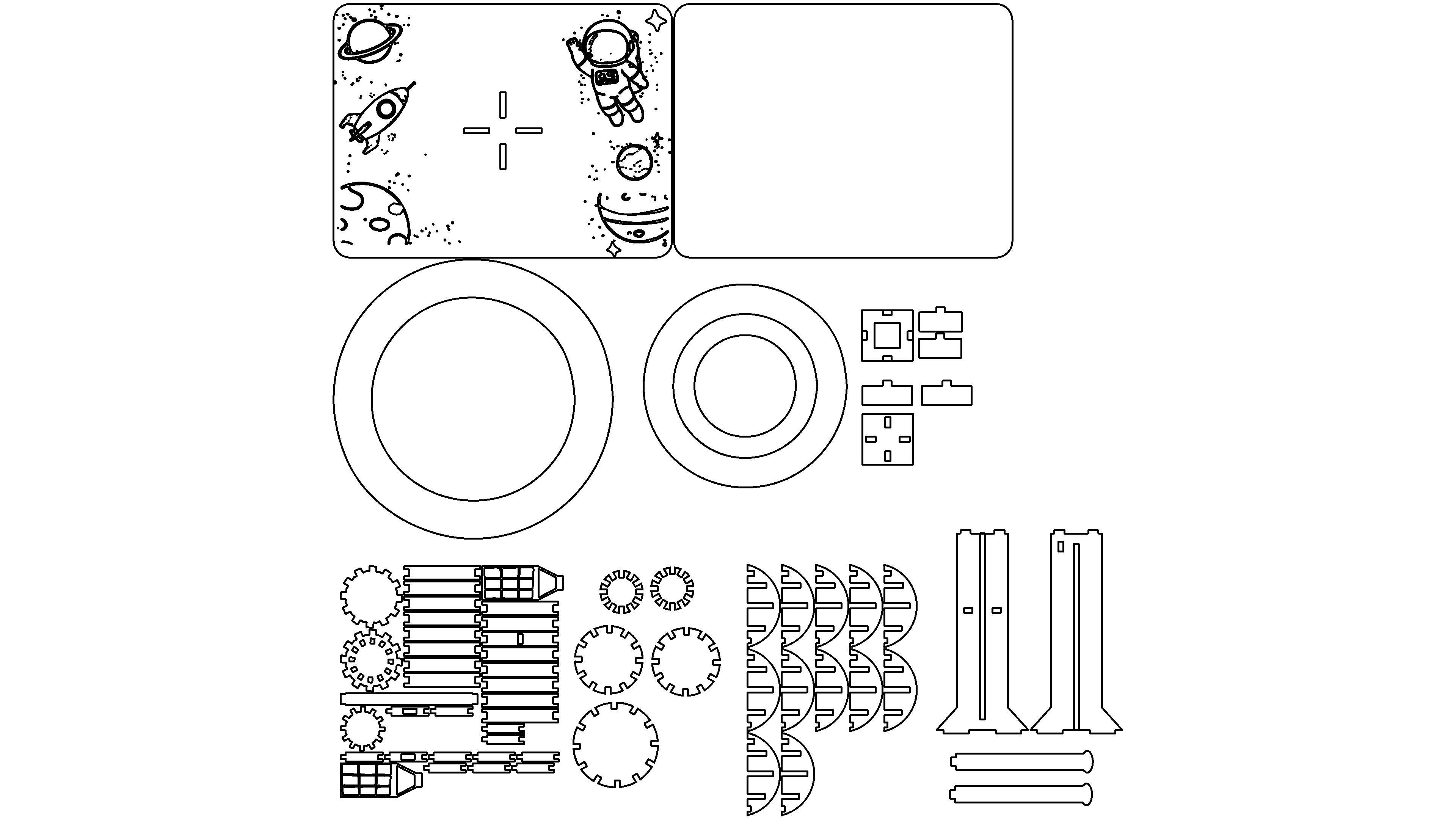
drawing documents
Xinghang Dream Post
Basic Parameters
process parameters
| Processing Technology | processed material | pattern | power(%) | speed(mm/s) | processing times |
|---|---|---|---|---|---|
| Draw lines | 3mmBasswood board | Horizontal unidirectional | 7 | 300 | 1 |
| cutting | 3mmBasswood board | Horizontal unidirectional | 99 | 40 | 1 |
ring
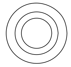
step1Draw the first circle
Select the circular tool on the left toolbar, hold down the left mouse button on the canvas and drag to draw the outermost circle.
step2Draw subsequent concentric circles
Keep the circle tool selected, draw the inner circles one by one with the center of the first circle as the reference point, control the size of each circle, and create a nested concentric circle effect.
step3: Save
After completion, click the "Save" button at the top to save the drawn file.
base
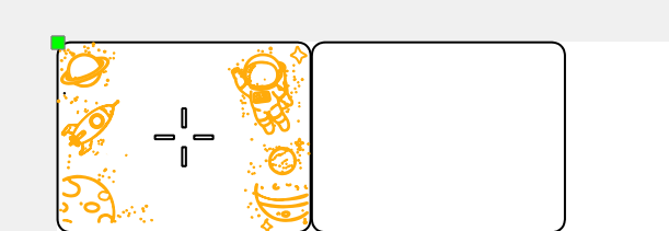
Step 1: Draw a rounded rectangle around the outer frame
1. Select the rectangle tool on the left toolbar.
2. Drag the mouse on the canvas to draw a rectangle.
3. Adjust the rectangle fillet parameters to make it a rounded rectangle.
Step 2: Draw various space elements
Generate the selected image using contour extraction function and adjust its position.
Step 3: Save the file
Click the "Save" button at the top to complete the drawing
Center pillar
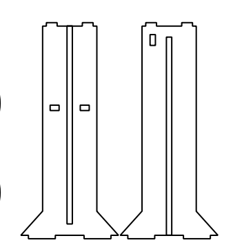
step 1Draw the outer contour of the left column
Select the rectangle tool and draw the main rectangle of the column.
Select the rectangle tool, draw a small rectangle, adjust it to the top of the large rectangle, and draw it Convex The top structure of the glyph, select three rectangles and click "Merge"; Similarly, draw the bottom structure of the trapezoidal extension to form the outer contour of the left column, and then click "Merge".
step 2Draw the internal details of the left column
Middle hole: Select the rectangle tool and draw a vertical rectangle inside the column as the dividing line in the middle.
Rectangular hole: Select the rectangle tool, draw multiple small rectangles separately, and place them in the corresponding positions of the column.
step 3Draw the outer contour of the right column
Copy the outer contour and inner details of the left column, and then adjust its position to symmetrically distribute with the left column to form the outer contour of the right column.
Use the rectangle tool again to draw a small rectangle and adjust its position.
step 4: Adjustment and Alignment
Select all elements and manually fine tune them to ensure that the positions of the two columns are symmetrical and the proportions of internal details are coordinated.
step 5: Save file
Click on the top Save " Button.
Earth
1、 Draw a basic circle
step 1Draw a basic circle
Select the circular tool and draw circles of different sizes (total) 5 One, corresponding to three sizes: large, medium, and small. Make sure the circle is neat when drawing.
step 2Add gear teeth
Select the rectangle tool and draw a small rectangle as Teeth.
For each circle, arrange small rectangles along the edges of the circle to ensure even spacing between teeth, forming a toothed structure of the gear.
Different sizes of circles correspond to different numbers of teeth, and the corresponding style can be matched by adjusting the size of the rectangle.
2、 Draw the right half circle combination structure
step 1Draw a single semi-circular unit
Select the circular tool, draw a perfect circle, and use the rubber break function to cut it into a semicircle.
Draw a vertical rectangle inside the semicircle using the rectangle tool (as the dividing line in the middle) to form a single semicircle unit.
step 2Batch Copy and Arrange
Select a single semi-circular unit and batch copy multiple identical units.
Layout according to rows and columns(3 line 5 Arrange these semi-circular units in sequence, paying attention to the difference in the number of rows at the bottom, to ensure alignment.
3、 Overall adjustment and saving
Select all elements, fine tune the position and size, and ensure that the layout of the left gear type structure and the right semicircle combination structure are consistent.
Click on the top Save " Button, complete drawing.
satellite
1、 Draw gear module
Basic Circle: Draw with Circle Tool 3 Make sure to draw regular circles of different sizes.
Add gear teeth: Use the rectangle tool to draw a small rectangle as Teeth ", for each circle, arrange small rectangles in an equal array along the edges of the circle to form a toothed structure of gears (the teeth of the middle gear are denser, and the number and spacing of rectangles need to be adjusted).
2、 Draw a long rectangular module
Long rectangle: Use rectangle tools to draw multiple long rectangles and adjust their length and width.
Short rectangles and details: Use rectangle tools to draw small rectangles and place them on a long strip as connections or detail blocks.
3、 Draw cone block module
Cone shaped body: Draw a trapezoid with a straight line tool and then modify it to a conical contour; Draw the interior with the rectangle tool Grid like Small rectangles (multiple small rectangles pieced together to create a grid effect).
Combination and replication: Combine cones with grid rectangles to create another identical cone block, adjust the position to connect with the elongated module.
4、 Overall layout and adjustment
Align the gear module, rectangular module, and conical block module according to the example positions, fine tune the size and spacing of each element to ensure structural coordination.
5、 Save file
Click on the top Save " Button.
comment (1)
-
classification
Aerospace themed competition event -
copyright
open source licenseCC-BY-NCProhibit commercial use; -
Business License
Further information

WeChat users_51
2025-12-5 15:41
Great Hahaha, hahaha, hahaha, hahaha